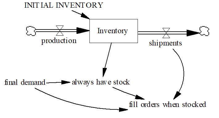
You enter Reality Check equations the same way you enter normal model equations. In the Text Editor, you simply type them in. In the Sketch Editor, you can enter them in diagrams by showing all of the elements to be checked as causes of the Test Inputs and Constraints. The Test Inputs and Constraints are not part of the model's causal structure. In addition, the right hand side of alternative defining equations in Test Inputs are not shown as causes of the variable being given the Test Input. Thus the equations:
Inventory = INTEG(production-shipments,INITIAL_INVENTORY) ~~|
always have stock :TEST INPUT: Inventory = 3*final demand ~~|
| fill orders when stocked :THE CONDITION: always have stock |
| :IMPLIES: shipments >= final demand ~~| |
would appear on the diagram as:

In it is likely that you will want to keep the equations and causal structure used in defining Reality Check equations separate from the normal model equations. One convenient way to do this is to put them in a separate group and include them on separate views.
In the diagram, the mixing of the different types of names can be confusing. When looking for arrows going in to fill orders when stocked, it is not what causes fill orders when stocked that is wanted, but what we need to know to determine if this is true. Given the difficulties of understanding diagrams just showing causal connections and flows, you may want to omit this added complexity from the working diagram. It is probably easiest to place Reality Check equations in a separate view so they will not be confused with model structure.
It can also be very convenient to adopt a naming conversion for Reality Check statements. For example you might start all Test Inputs with TI and all Constraints with RC.